
FIR filter design in Clash
In this post I will design a series of digital filter circuits in the functional hardware description language Clash.
This is the first in a series of blog posts, in which I plan to design an AM radio receiver in Clash, flash it to the FPGA on my BladeRF, and use it to listen to AM radio!
It will basically be a digital hardware version of my software AM receiver built using the library described in my previous blog post.
Background: the BladeRF
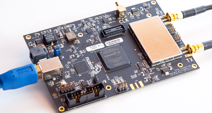
The BladeRF is a software defined radio platform designed for hobbyists. Like the RTLSDR, it contains an analogue frontend that filters the incoming signal to select a block of frequencies, mixes the filtered signal down and then digitises it with an analogue to digital converter. The digitised signal is made available to software through the USB connection.
Unlike the RTLSDR, it is capable of much higher sampling rates, a larger frequency range, and, most importantly, it can do all or this in reverse to transmit data as well. However, the feature we will be most interested in for this blog post is the on-board FPGA. The signal pass through the FPGA after being digitised and before they are sent to the computer over USB. This allows us to perform high speed signal processing on the FPGA before the samples even make it to software land.
FIR filters
If you have read my previous blog post, you will know that the first thing I will need is a filter to select only the signal of interest. This first post will focus only on the design of the filter.
FIR (finite impulse response) filters have a straightforward implementation in hardware so we will use one of those. A FIR filter basically takes successive dot products of the input data with a vector of coefficients. The most obvious way of implementing such a filter is called the direct form and it looks something like this:

The circuit keeps copies of the input signal delayed from 1 to N clock cycles, multiplies each delayed copy by a filter coefficient and sums them up. The Clash implementation is straightforward. Based on the design on the Clash website:
import CLaSH.Prelude

basicFIR :: (Num a, KnownNat (n + 1), KnownNat n) => Vec (n + 1) a -> Signal a -> Signal a
basicFIR coeffs x = dotp (pure <$> coeffs) (iterateI (register 0) x)
  where
    dotp as bs = fold (+) (zipWith (*) as bs)

topEntity :: Signal (Signed 16) -> Signal (Signed 16)
topEntity = basicFIR (3 :> 5 :> 7 :> 9 :> Nil)
Turning this into actual logic gates is straightforward with clash:
$ clash --verilog basicFIR.hs
This creates a folder called verilog which contains the generated Verilog. As is usually the case with generated code it is pretty difficult to read. If you have the patience, you can read it and verify that it really does describe exactly the direct form in the diagram above. However, there is an easier way…
The excellent Yosys synthesis suite allows us to read the generated Verilog, flatten the design, throw away unused and intermediate signals and render the design as a graph using Dot.
$ yosys

> read_verilog *.v
> hierarchy; proc; flatten; opt; opt_clean -purge
> show Main_topEntity
And we get…

(You probably want to right click and view image so you can see it properly).
Examining the logic, it is clear that this is exactly what we wanted. The adders are arranged in a tree on the right. The leftmost side of the adders is fed from the multipliers sitting around the middle of the design, one for each coefficient. Lastly, the three registers at the bottom left create the delayed versions of the input samples.
Genericity
Although this is a trivial design, the power of Clash is already clear. We did in four lines of code something that would take many more in Verilog. And, the design is generic in both the type of the data being filtered and the number of filter taps.
We can easily change the filtered data type. Perhaps we want to use Clash’s fixed point data type:
topEntity :: Signal (SFixed 8 8) -> Signal (SFixed 8 8)
topEntity = fir (3 :> 5 :> 7 :> 9 :> Nil)
Or maybe we want to increase the number of filter taps:
topEntity :: Signal (Signed 16) -> Signal (Signed 16)
topEntity = fir (3 :> 5 :> 7 :> 9 :> 11 :> 13 :> 15 :> Nil)
In each case, when examining the generated schematic we see that Clash generates exactly the logic we want.
Higher order functions
Perhaps the most powerful feature of Clash, however, is the use of higher order functions (functions that take other functions as arguments) and the clarity and conciseness these bring to the code. In the example above, I used the higher order functions iterateI, fold, and zipWith. If you click on the links there are nice little diagrams that show the circuit structure that these higher order functions will synthesize to.
For example, the iterateI function which we use to generate the progressively delayed input samples has the structure:

If we substitute the f with our delay function (in Clash: “iterateI (register 0)” - see above) we get exactly the top line of the filter block diagram at the beginning of this section.
Building your circuits using higher order functions in this way makes the structure of the circuit obvious to anyone familiar with Haskell/Clash who reads your code. It also prevents mistakes that can arise when implementing these structures manually (for example, using for … generate loops in VHDL) in much the same way that using higher order functions can prevent mistakes when writing software.
A Faster Filter
The direct form has a major shortcoming, however. While the adder tree has depth logarithmic in the number of filter taps, for larger filters, this is still often too deep. Alternatively, we can move the registers to after each summation to break up this large combinational path. This is called the transpose of the filter and it looks like this:

It can be implemented in Clash as:
fastFIR :: (Num a, KnownNat (n + 1)) => Vec (n + 1) a -> Signal a -> Signal a
fastFIR coeffs x = foldl func 0 $ map (* x) (pure <$> coeffs)
    where
    func accum x = register 0 $ accum + x
In this design, there is no combinational delay longer that a multiplier followed by an adder. However, this may even be too much, or our FPGA architecture may force us to latch immediately after a multiplication if we want to use a DSP block. Since Clash provides us with direct control over the generated logic this is not difficult to overcome:
fastFIR :: (Num a, KnownNat (n + 1)) => Vec (n + 1) a -> Signal a -> Signal a
fastFIR coeffs x = foldl func 0 $ map (register 0) $ map (* x) (pure <$> coeffs)
    where
    func accum x = register 0 $ accum + x
Note the additional “map (register 0)”.
…and the generated logic:

It is clear from the diagram that the longest combinational logic path is now a single multiply.
Testing
It should be obvious from the schematic that the design is correct. However, real world designs are more complex than a single FIR filter and some kind of testing is usually needed. We can write a simple quickcheck property that tests that for all inputs (the filter coefficients and input samples), the basic FIR filter and the optimised one generate the same outputs.
import qualified Prelude
import Test.QuickCheck
import CLaSH.Prelude

import BasicFIR
import FastFIRRegistered

propFilter :: (KnownNat (n + 1), KnownNat n) => Vec (n + 1) (Signed 32) -> [Signed 32] -> Bool
propFilter coeffs input =
       Prelude.take (Prelude.length input) (simulate (basicFIR coeffs) input)
    == Prelude.take (Prelude.length input) (Prelude.drop 2 (simulate (fastFIRRegistered (reverse coeffs)) input))

main = quickCheck (propFilter :: Vec 8 (Signed 32) -> [Signed 32] -> Bool)
We need to account for the fact that the fastFIR filter actually applies the coefficients in the opposite order to the basic one (have a look at the schematic to convince yourself), so we reverse the coefficients before running it. Also, the additional registering in the faster version means that the output is delayed by two cycles, so we account for this by dropping the first 2 outputs of the optimised filter.
Compiling with Clash and running it gives:
$ clash fastfilterTest.hs
$ ./fastFilterTest;
+++ OK, passed 100 tests.
Success!
The first time I ran this test, I had not realised that the filter coefficients needed to be reversed. Obviously the test failed. Quickcheck can print the failing testcase. However, by default, it actually does something even better. It ‘shrinks’ the parameters to the property to find the simplest arguments that case the property to fail:
*** Failed! Falsifiable (after 2 tests and 30 shrinks):
<0,1880609307,0,0,0,1512831568,1992364421,766093847>
[1]
It managed to find a single element input vector “[1]” for which the outputs differed. It also printed out the filter coefficients for which the test failed. Unfortunately, it was not able to shrink the coefficients as the type signature forces them to be an 8 element vector. There is a nice explanation of shrinking here.
Once you have a simple counterexample, it is straightforward to open up the Clash repl and debug it.
Linear phase
Most of the filters in my software AM radio are linear phase. This means that the filter coefficients are symmetric. That is, the first half of them are the same as the second half reversed. We can exploit this property to halve the number of multipliers needed.
Multipliers are a scarce resource on the BladeRF. With only 200 of them, we must exploit any available properties of our design in order to reduce the number we require.
The coefficients are symmetric, so, for example, the first coefficient is the same as the last one. The summation contains the terms (c[1] . x[n]) and (c[N] . x[n-N]) where c is the vector of coefficients, x is the vector of input samples, N is the filter length and n is the current sample index. This can be factored as (x[n] + x[N]) . c[1] (since c[1] == c[N]), saving a multiplication.
The implementation is given below. Skip ahead to the schematic if it is unclear.
import CLaSH.Prelude

linearPhase :: (KnownNat (n + 1), Num a) => Vec (n + 1) a -> Signal a -> Signal a
linearPhase coeffs x = foldl func 0 $ zipWith (*) folded (pure <$> coeffs)
    where
    func accum x = register 0 $ accum + x
    folded       = map (+ x) delayed
    delayed      = iterate (lengthS coeffs) (register 0 . register 0) (register 0 x)

topEntity :: Signal (Signed 16) -> Signal (Signed 16)
topEntity = linearPhase (3 :> 5 :> 7 :> Nil)
…and the generated logic:

Note that the longest combinational delay has grown to be an adder, followed by a multiplier, followed by another adder. As an exercise, see if you can shrink that back to a single multiply.
Testing
Again, we test it.
import qualified Prelude
import Test.QuickCheck
import CLaSH.Prelude

import BasicFIR
import LinearPhase

propFilter :: Vec 64 (Signed 32) -> [Signed 32] -> Bool
propFilter coeffs input =
       Prelude.take (Prelude.length input) (simulate (register 0 . basicFIR (reverse coeffs ++ coeffs)) input)
    == Prelude.take (Prelude.length input) (simulate (linearPhase coeffs) input)

main = quickCheck (propFilter :: Vec 64 (Signed 32) -> [Signed 32] -> Bool)
We make sure that it is equivalent to the basic filter applied to the concatenation of the coefficients with themselves reversed. As above, we allow for the difference in delays by dropping the first couple of input samples.
And again:
$ clash linearPhaseTest.hs
$ ./linearPhaseTest
+++ OK, passed 100 tests.
Conclusion
I hope that this post has demonstrated the power of Clash. Clash designs are, in my experience, more concise and more generic than the equivalent design in VHDL or Verilog. Higher order functions make the code more readable and less likely to contain faults.
Testing is also vastly improved with Clash. Since Clash code is just Haskell code, you have the full Haskell testing infrastructure at your disposal, including the famous QuickCheck.
Probably the most important attribute, though, for a new HDL to compete with VHDL and Verilog is that it gives the engineer full control over the generated logic. Clash was designed for this, and, as I hope this post has demonstrated, Clash achieves this admirably.
Admittedly, FIR filters are not particularly complex. However, I am confident that all of these advantages will scale to more complex designs.
Acknowledgements
Thanks to Christiaan Baaij for the high level filter block diagrams.
Code
The code in this blog post can be found here.